INTRODUCTION
This comprehensive overview establishes the fundamental theoretical concepts necessary for a profound understanding of the tutorial for the airflow around the NACA0012 & NACA2412 airfoil at different angles of attack. Key principles include the nature of airfoils, the influence of the angle of attack on lift and drag, and the critical phenomenon of stall.
KEYWORDS RECAP
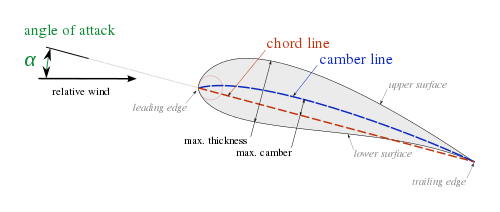
1. Airfoil Definition:
An airfoil, also known as an aerofoil, is a streamlined body capable of generating significantly more lift than drag when moving through a fluid. This is achieved by deflecting the oncoming fluid, resulting in aerodynamic forces.
2. Aerodynamic Forces:
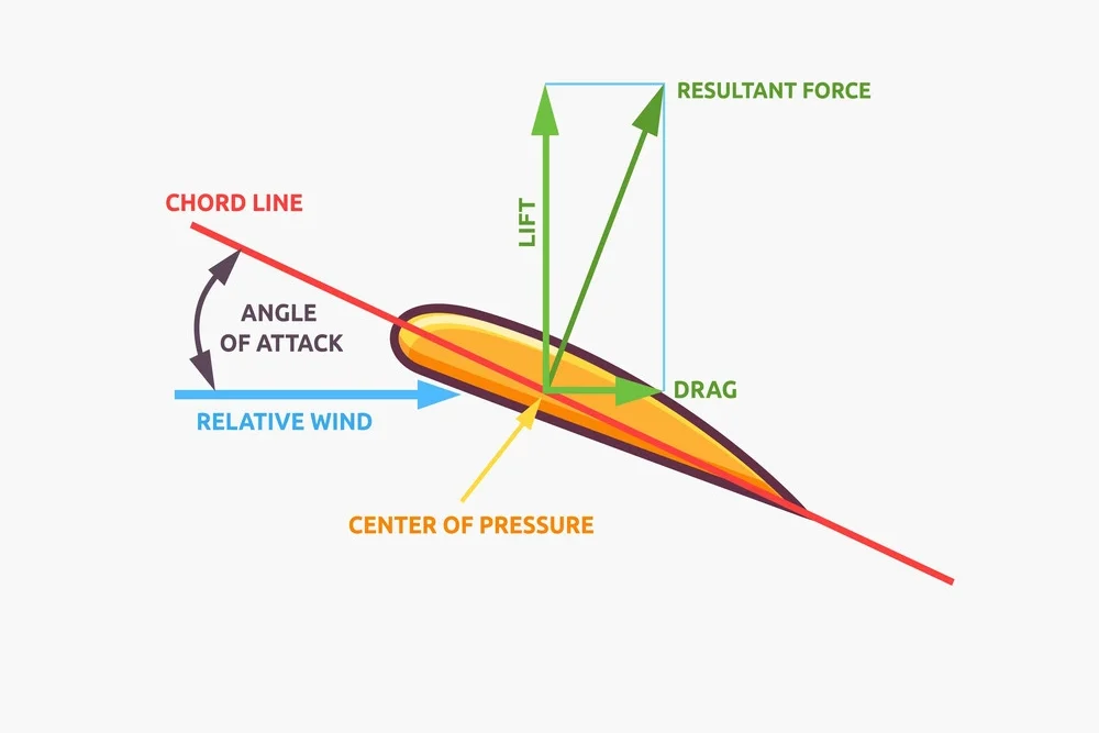
When a solid body, like an airfoil, moves through a fluid, it experiences aerodynamic forces. These forces, primarily lift and drag, are influenced by the angle of attack, a crucial parameter in airfoil behavior.
3. Lift Generation:
The lift on an airfoil is primarily a result of its angle of attack. While most foil shapes require a positive angle of attack for lift, cambered airfoils can generate lift even at a zero angle of attack.
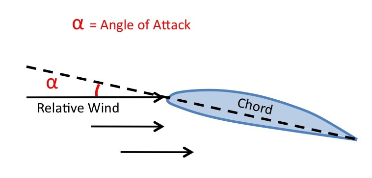
4. Angle of Attack Definition:
The angle of attack is the angle formed by the chord of the airfoil and the direction of the relative wind or the vector representing the relative motion between the aircraft and the atmosphere.
5. Effect of Angle of Attack:
Increasing the angle of attack leads to a proportional increase in both lift and induced drag, up to a certain point. However, excessive angle of attack, typically around 17 degrees, can cause airflow detachment and result in a loss of lift, known as a stall.
6. Stall Phenomenon:
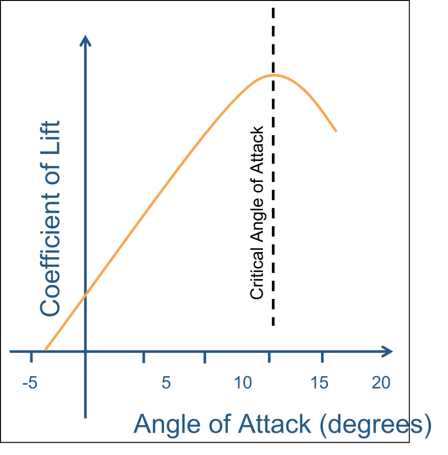
A stall occurs when the angle of attack becomes too high, causing airflow separation on the upper surface of the airfoil. This leads to a loss of lift, emphasizing the critical importance of understanding and avoiding stalling conditions.
7. Symmetric vs. Cambered Airfoils:
Symmetric airfoils, like NACA0012, have identical upper and lower surfaces, ideal for certain applications. In contrast, cambered airfoils, exemplified by NACA2412, have a curvature, generating lift even at zero angle of attack.
The NACA (National Advisory Committee for Aeronautics) naming convention for airfoils consists of a four-digit code. Each digit in the code corresponds to specific characteristics of the airfoil. The format is NACA-ABCD, where:
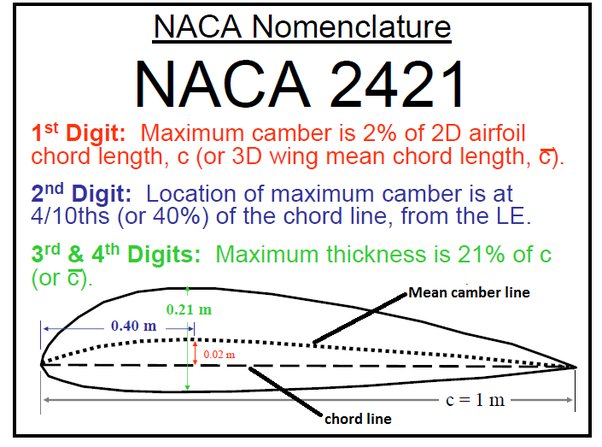
- NACA: Indicates that the following digits represent an airfoil designation by the National Advisory Committee for Aeronautics.
- A: Represents the maximum camber of the airfoil, expressed as a percentage of the chord length. For example, if A = 2, the maximum camber is 2% of the chord.
- B: Denotes the location of the maximum camber, expressed as a percentage of the chord length. For instance, if B = 4, the maximum camber occurs at 40% of the chord from the leading edge.
- C: Indicates the thickness-to-chord ratio, expressed as a percentage. If C = 12, the airfoil has a thickness that is 12% of the chord length.
- D: Specifies the type of airfoil. Symmetrical airfoils have D = 0, while cambered airfoils have D = a non-zero value.
As an example, consider the NACA0012 airfoil:
- A = 0: Indicates zero camber, as it is a symmetric airfoil.
- B = 0: Since there is no camber, the location of the maximum camber is irrelevant.
- C = 12: Represents a thickness-to-chord ratio of 12%, indicating the airfoil’s thickness.
- D = 0: Specifies that it is a symmetric airfoil.
In contrast, for the NACA2412 airfoil:
- A = 2: Indicates a maximum camber of 2% of the chord.
- B = 4: Specifies that the maximum camber occurs at 40% of the chord.
- C = 12: Represents a thickness-to-chord ratio of 12%, indicating the airfoil’s thickness.
- D = 1: Indicates that it is a cambered airfoil.
This naming convention allows engineers and researchers to easily identify and communicate the key characteristics of a specific airfoil, aiding in aerodynamic analysis and design.
CONCLUSION
By integrating these fundamental principles into the theoretical foundation that you have got from your class, this recap provides a framework for approaching the tutorial on the flow characteristics around the NACA0012 airfoil at various angles of attack.